Sound level meter project
The goal of this project is to design a sound level meter and a Python user interface to display the measurements in a clearer way. To achieve this, we followed several precise steps for creating the sound level meter, which uses green, yellow, and red LEDs to indicate the noise level. At the same time, we worked on the design of the user interface.
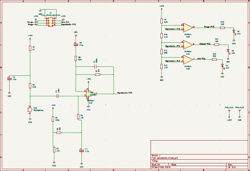
Understanding the sound level meter circuit
The goal of this step is to understand how the provided sound level meter circuit works, in order to execute the following steps more effectively.
Resources used
Educational: explanations about the circuit functioning
Trace
Self-assessment


Understanding the overall functioning of this circuit was quite simple thanks to Mr. Laurent's (teacher) clear and straightforward explanation.
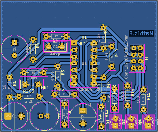
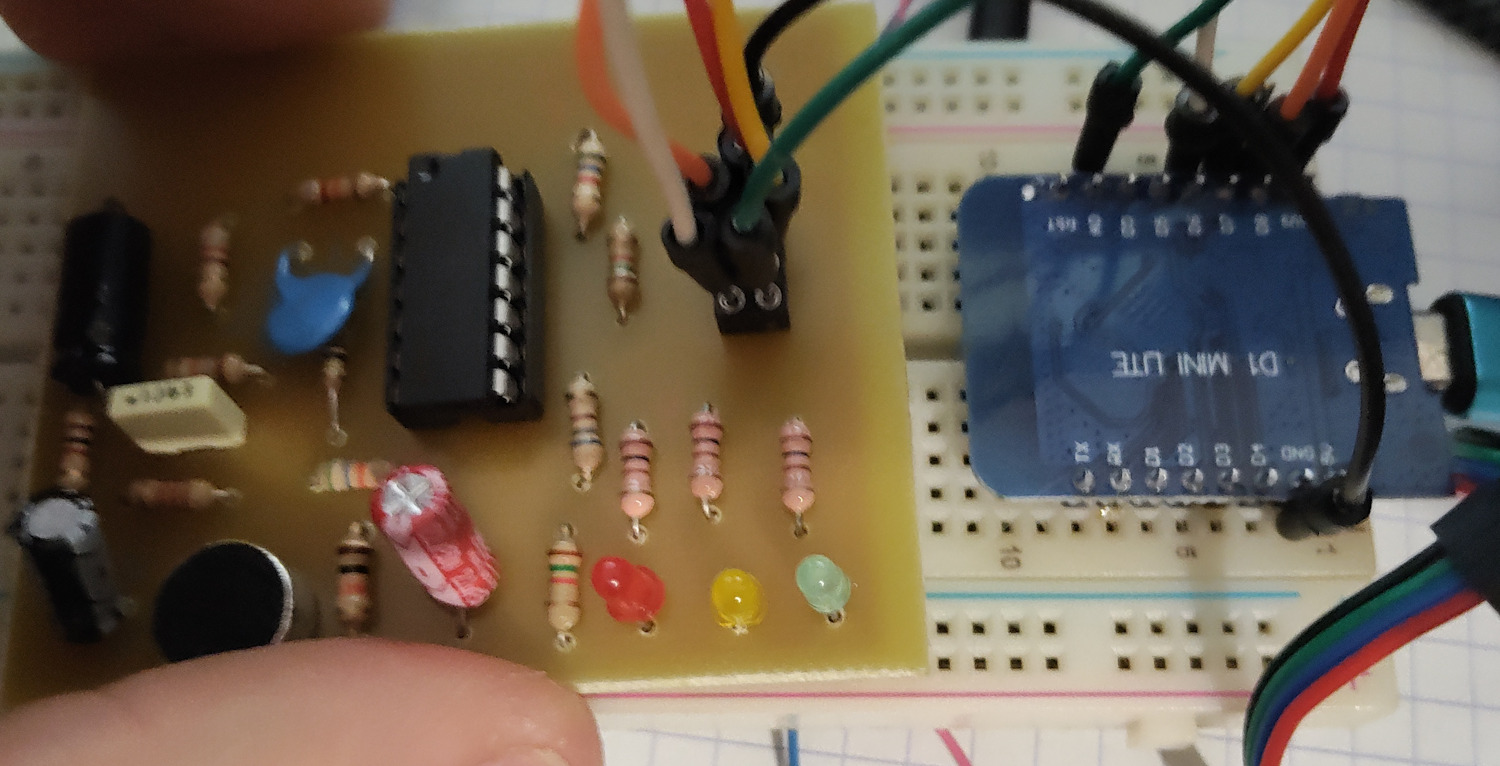
Creating the PCB
This step involved creating the sound level meter's board by positioning the various components and routing the tracks between them, ensuring the correct track sizes for each component.
Resources used
Educational: training on KiCad by an instructor
Trace
Self-assessment

Creating this circuit posed no issues for me, despite it being my first experience with this software.
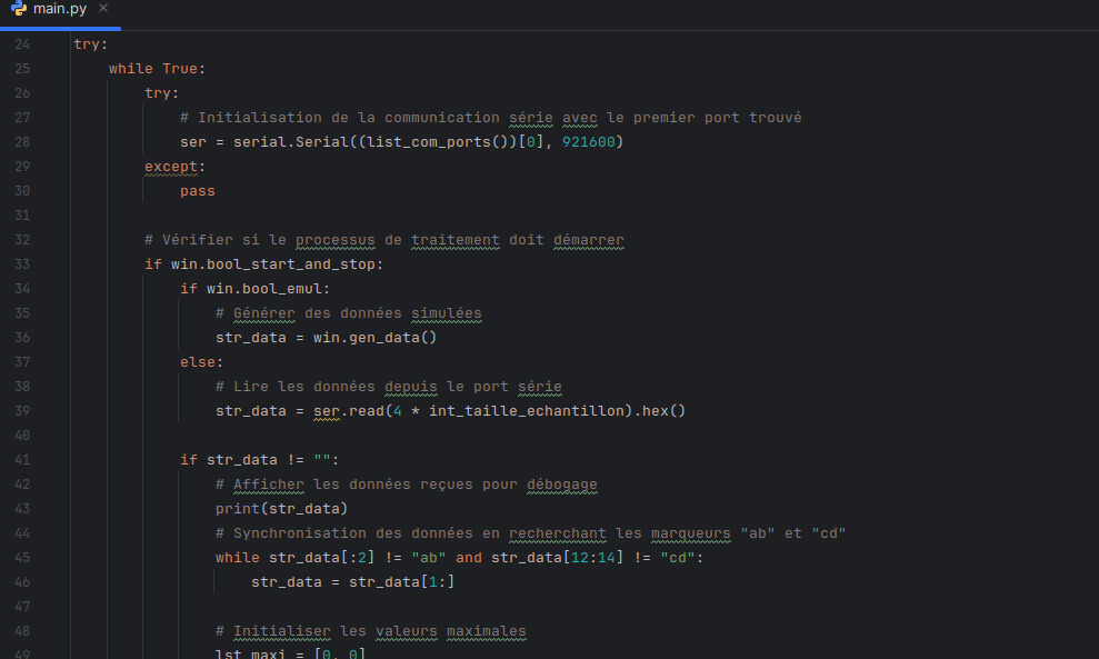
Processing the frame received from the STM32
This step consisted of converting the frame received from the STM32 into exploitable data to display later on a 2D interface.
Trace
Self-assessment
Coding this part of the application was simple.
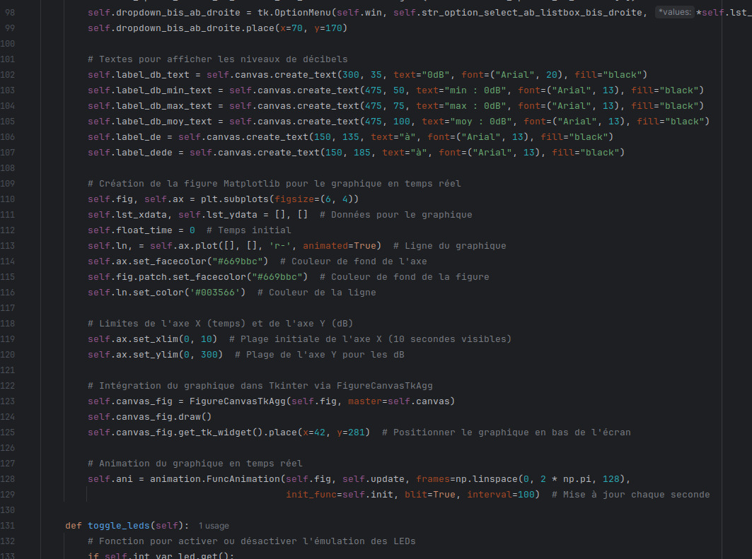
Connecting the translated frame to the UI
This step consisted of creating an interface to visualize the translated data and linking the two together.
Trace
Self-assessment
This part of the code posed no problems for me.
Recreating the frame processor received from the STM32
In this step, I worked on recreating the previously provided frame processor from scratch. I had to understand how the sound level meter outputs worked to convert them into hexadecimal.
Resources used
Internet: documentation on analog input encoding for a D1 mini lite
Trace
Self-assessment
For this step, I had to document myself to understand how analog inputs worked. Apart from that, the coding was not an issue.
Conclusion
This project allowed me to develop my skills in report design, HMI interface integration, maintenance with commented code, as well as designing code effectively and verifying functionality through tests.